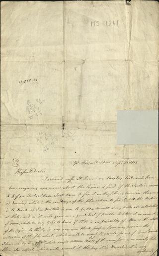
Letter from Henry Maudslay to Mr Matthew Murray, Engineer
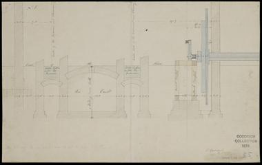
Drawing of engine house, cross section
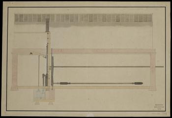
Design for the steam engine for metal mills, longitudinal section of foundry

Drawing of engine house, section of boiler seating and stokehole
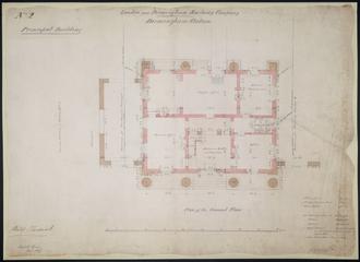
Drawing of Curzon Street Station, Birmingham (London & Birmingham Railway), showing ground floor plan of the principal building, by signed Philip Hardwick, Grissell and Peto
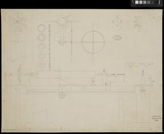
Drawing of treenail and coak making lathe
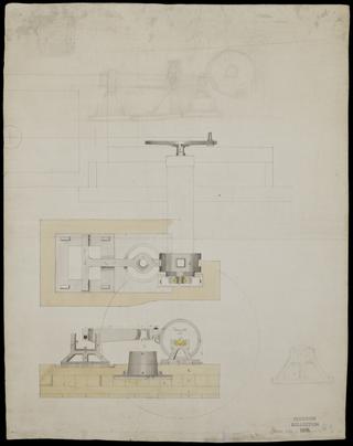
Drawing of forge hammer from Birmingham by Robert Roberts
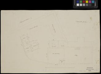
Ground plan of building of Kings Mills at Portsmouth

Copy sketch of Mr Heppenstall's spinning frame for rope yarn
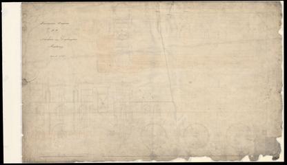
Drawing of Locomotive Engine for the Stockton and Darlington Railway
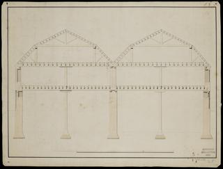
Section of building over Coal Yard, Metal Mills, Portsmouth
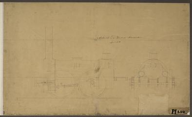
Mohawk and Hudson Locomotive drawing
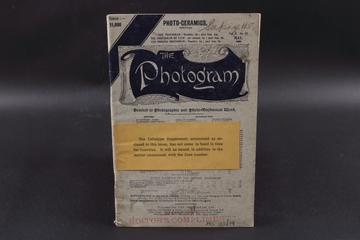
An edition of 'The Photogram' journal vol. 2 no. 17

Drawing of Curzon Street Station, Birmingham (London & Birmingham Railway), showing front elevation of the principal building, signed by Philip Hardwick, Grissell and Peto
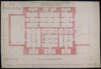
Drawing of Curzon Street Station, Birmingham (London & Birmingham Railway), showing plan of the basement walls of the principal building, signed by Philip Hardwick, Grissell and Peto
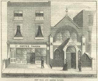
Railway Signal Volume 3 (1885)

Drawing of Curzon Street Station, Birmingham (London & Birmingham Railway), showing section through Entrance and traffic office, signed by Philip Hardwick, Grissell and Peto
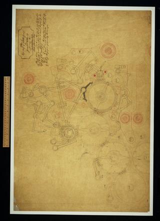
Plan of left half of middle group for General Plan 28.
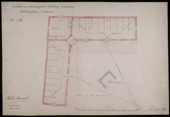
Drawing of Curzon Street Station, Birmingham (London & Birmingham Railway), showing plan of Birmingham Station's stables, signed by Philip Hardwick, Grissell and Peto
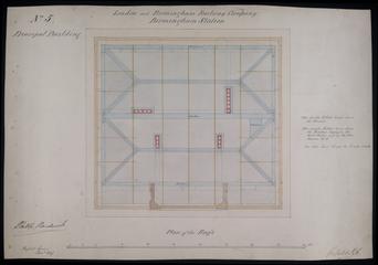
Drawing of Curzon Street Station, Birmingham (London & Birmingham Railway), showing details of roof including gutters, binders, trusses and lead work, signed by Philip Hardwick
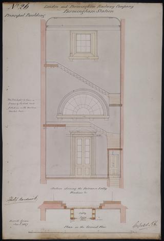
Drawing of Curzon Street Station, Birmingham (London & Birmingham Railway), showing section of the entrance lobby to the principal building detailing windows and includes plan, signed by Philip Hardwick, Grissell and Peto
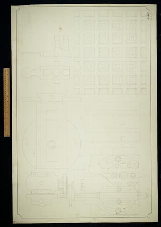
Small planing machine. Sheet 1.
![Pamphlet entitled ‘A Further Report, on the Intended Rail or Tram Road, from Stockton, by Darlington, to the collieries, with a branch to Yarum [sic]’](https://coimages.sciencemuseumgroup.org.uk/525/900/large_thumbnail_rais_3_6_1_000.jpg)
Pamphlet entitled ‘A Further Report, on the Intended Rail or Tram Road, from Stockton, by Darlington, to the collieries, with a branch to Yarum [sic]’
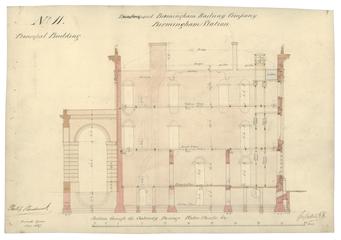
Drawing of Curzon Street Station, Birmingham (London & Birmingham Railway), showing section through the gateway passage and water closets, signed by Philip Hardwick, Grissell and Peto

Drawing of Curzon Street Station, Birmingham (London & Birmingham Railway), showing elevation of the flanks of the building, signed by Philip Hardwick of Grissell and Peto
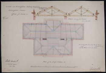
Drawing of Curzon Street Station, Birmingham (London & Birmingham Railway), showing plan of roofs and gutters of offices for goods, signed by Philip Hardwick, Grissell and Peto
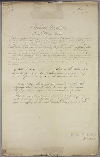
Multiplication. Sheet 1 of 4.

Plan of a proposed alteration to locomotive engines

Plan of operation and variable card counting apparatus. Suited to Plans 28 and 28a.
![Drawing of Tender for the Magnet Loco Engine, No. 108 Two end sections showing wheels, axle boxes and brake arrangement, [presumably for new tender-patent drawing]](https://coimages.sciencemuseumgroup.org.uk/83/229/large_thumbnail_19124_3.jpg)
Drawing of Tender for the Magnet Loco Engine, No. 108 Two end sections showing wheels, axle boxes and brake arrangement, [presumably for new tender-patent drawing]
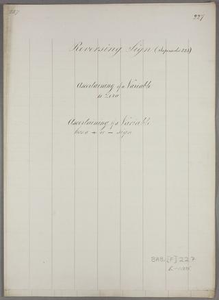
Reversing sign ascertaining if a variable is zero, ascertaining if a variable has a + or - sign (supersedes 223).
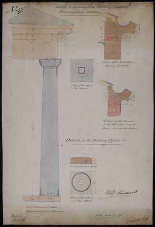
Drawing of Curzon Street Station, Birmingham (London & Birmingham Railway), showing details of the Birmingham Station's booking offices, signed by Philip Hardwick, Grissell and Peto
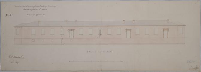
Drawing of Curzon Street Station, Birmingham (London & Birmingham Railway), showing elevation of booking office next to rails
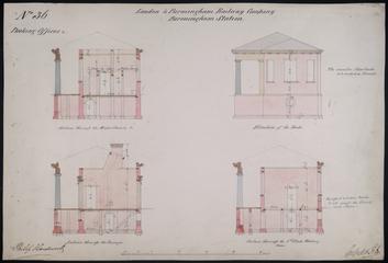
Drawing of Curzon Street Station, Birmingham (London & Birmingham Railway), showing side elevation of booking office with sectional drawings through water closets, passages and first class waiting room, signed by Philip Hardwick, Grissell and Peto.

Plan and elevation of sundry parts in the upper cages of left half of middle group.

Long pinions in the position for adding. Adding wheels and short pinions behind long pinions.
Multiplication.
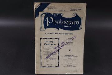
An edition of 'The Photogram' journal vol. 5 no. 50
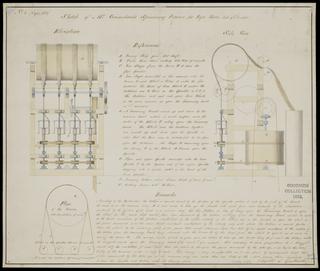
Copy sketch of Mr Grimshaw's spinning frame for rope yarn

Method of grouping for the large machine.

Verticals for approximative division. Sheet 2 of 4.
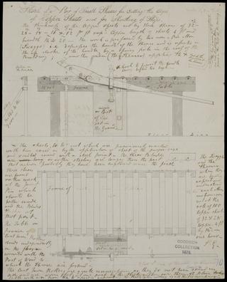
Sketch of a pair of small shears for cutting the edges of copper sheets used for the sheating of ships

Drawing of Curzon Street Station, Birmingham (London & Birmingham Railway), showing elevation of the Offices for Goods from the road, signed by Philip Hardwick, Grissell and Peto .

Drawing of Curzon Street Station, Birmingham (London & Birmingham Railway), showing plan of roofs and gutters at Birmingham Station with sectional drawings showing truss over stables and the truss over harness room
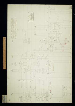
Elevation of parts of the card counting apparatus for operation and variable cards.
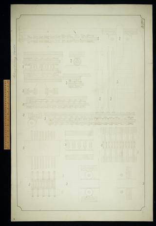
Sections of framing and racks. Sheet 6.
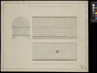
Drawings of boiler for 56 Horse steam engine at the Metal Mills, Portsmouth
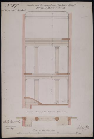
Drawing of Curzon Street Station, Birmingham (London & Birmingham Railway), showing section of principal building showing pilasters and columns along with a plan of the same area on first floor, signed by Philip Hardwick, Grissell and Peto
